GW11-psu
GW11 power supply:
Vcc uses TPS78233 for Vcc (ie dig supply) this works up to 6V input, +-0.3V regulation, drops 250mV max, typ. 86mV noise. ON all the time.
Vcs (analogue sensors) uses TPS76833 for 3.3V, disabled to 1uA sleep by MSP, dropout 350-575mV,
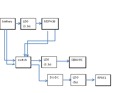
Vreadio is from DC-DC step-up from BatV with TPS61032 to 5.2V (95% eff) then TPS76850 for 5V VCCR to RPM transceiver. followed by LDO to 3V for MCU etc
radio max for TX 85mA?
line regulation of the TPS61032 DCDC is 0.6% (30mV?)
BATTERY 3.7V  --> DC-DC(TO 5.xV)--> TPS76833(MSP430)-->SWITCHES(like max4751) --> TPS76850(RPM1, 5V)
                                                                               --> TPS76833(ANALOG SENSORS, 3.3V)
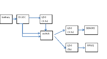
Option 2:
BatV -LDO-> 3V Vdigital
BatV -switch-> -LDO-> 3V Vanalogue (switchable OFF, separate for noise isolation)
BatV -DCDCbooster-> 5.2V -LDO-> 5V Vradio
we may move to 3V for digital and analogue side as that makes more use of low battery V?
note in this version the switches have less drain than the sleep modes of the other regs.

Royan's suggestions: use Vref IC to power bridges like strain. Need Switch for LDOs to reduce disable current
the gwdev board has a DC-DC TPS61032, which provides 5V (for radio). Followed by three regulators, TPS76850, and two TPS76833, for MSP430 microprocessor working voltage, and for the analogue sensors, both provide 3.3 volts.
GW10 used ADP3300 for Vanalogue. back to probe improvements
