GW12 Geophone Probe
Contents
Initial Geophone Plan and Strategy
current plan is to have three deep geophones (3 axis) at 90% depth and possibly some shallow single axis nodes.
Wired (serial) links will provide power to them as we can then gather more data without severe filtering/deletion and it removes some radio links from the systems for the initial 2012 trials.
Surface nodes linked in via RS485 will use faster 868MHz CC1120 radio to communcate to the base station.
A small ARM-cortex M3 based (ie EFM) surface seismic node has been designed for the task on the surface - with two CC1120 ports and the rs485. This can buffer data on its uSD card independantly.
Swiss Paper using Geophones to record basal glacier events
In the paper Basal icequakes during changing subglacial water pressures beneath Gornergletscher, Switzerland, three types of geophones are used in different configurations to record what they refer to as events. The three geophone types are:
- 1Hz, 3Dimensional (surface), 2004, Lennartz LE-3D
- 28Hz, 1Dimensional (deep-borehole), 2004, Geospace GS-20DH
- 8Hz, 1Dimensional (shallow-borehole), 2006, Geospace GS-11D
These devices are connected to a Geode which records the signals of multiple devices simultaneously using gains of 24dB (surface) and 36dB (borehole). Using an automatic self-trigger algorithm, events were recorded and appear to have been used to detect deep events.
The 2004 geophone deployment was active from the 15 June to the 8 July, while the 2006 deployment was active from 29 May to the 28 July.
The Hypocentre location of icequakes were found using a procedure described in Principles and Applications of Microearthquake Networks
Filter used in Signal Acquisition
2 simple filters were used for signal capture:
- Single-pole low pass filter at Nyquist frequency/2
- High-pass filter at 2Hz
Self-Trigger Mechanism
The signal recording was done using a self-trigger mechanism. This meant that when a signal was detected due to signal above a threshold from the previous data, the signal was recorded .
The trigger was shown to be not influenced by precipitation events, but to be influenced by meltwater runoff, and thus more active during the summer periods.
1D Geophone System Design
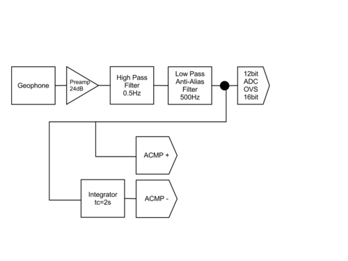
Geophone 1KHz 12-bit oversampled to 16-bit with complete stop anti-alaising filter at around 500Hz and high-pass filter at around 0.5Hz. Later reduced to 512 Hz sampling

The bottom half of the design in Figure 1 shows a technique used in numerous signal capturing designs which integrates the signal being measured over a time constant of 2 seconds. The actual signal is then compared to the integrated signal and if the signal is greater than the integrated signal plus an internal hysteresis value set by the MCU, signal capture is then triggered.
It is not clear whether the event detection should trigger capture of the signal, or whether the signal should continuously be captured, and only if this condition is met, write the data to flash. This was then investigated and we chose continuous adc with save-on-event..
3D Geophone System Design
The 3D Geophone system design is similar to the 1D design, except that the signals input to the ACMP are joined together for event detection.
PCB Microphone
As a pcb microphone has a minimum frequency response of around 100Hz. This means that one could also use a small pcb microphone to trigger the events. As this might not work well in the field, it would be a good idea to trial this in the first year by only capturing the microphone data for a comparison with the geophone data, and not triggering by it initially. Nice idea which was not used in the end as the real signals can be monitored anyway.
Physical Probe
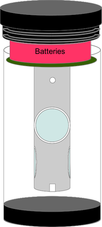
The geophone probes will be built in a 70mmm polycarbonate tube.
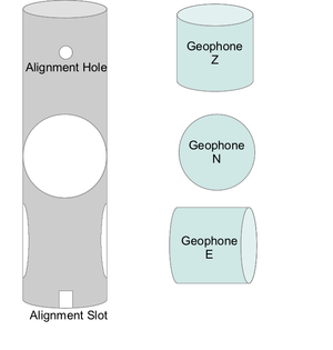
The Probe will contain 3x GS20DH Probes configures in a 3D setup. This will be achieved using a tube cut with two holes in it which forms the holder of the geophones. Hopefully the Mech workshop will help with this building this design. Initial thoughts: tube made from metal tube cut into a configuration shown in Figure 2. Later realised plastic water pipe was OK as it was encapsulated in resin afterwards.
The geophone tube then needs to be mechanically aligned in the casing with the PCB so that we have a guarantee of the orientation of the geophones from the IMU of the probe node. This is done with the alignment slots - A system needs to be brainstormed to ensure this is calculated correctly.
As the geophone will be recording more data, larger batteries are also required.


